|
|
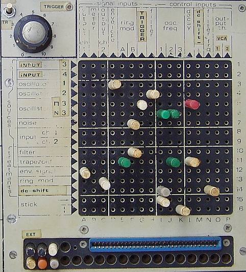
The control input line of the Reverb (M) is now the input of the DC shifter. The output of the Reverb (14) is now the output of the DC shifter. Lines (1) and (2) were the output channels, now spare inputs 3 and 4. |
| The AC-trigger circuit : |

|
|
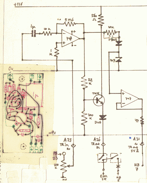
This module only needs an input, which came available by the spare input of the former Reverb (G). It was implemented, because of the spare corner to add a pot, and the quite clumsy application of producing an external trigger for the envelope shaper by loud sounds on output channel 2. That design led to complications if one wanted to work with a stereo-output as the audio-source. So I made an 'inside' connection to this. |