|
|
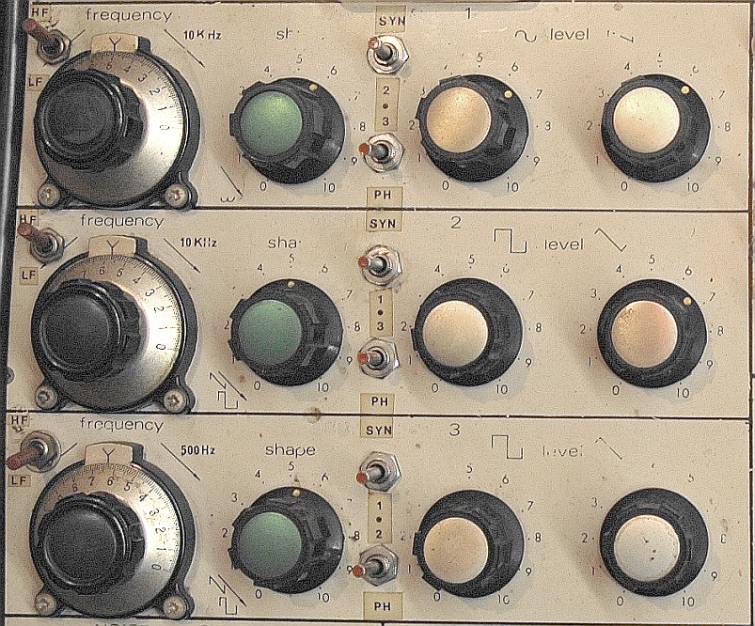
The three switches at the left are for the high or low frequency range. Originally osc. 3 was designed to be a 'LFO', but it appeared, that the circuitry of osc. 2 and osc. 3 was similar, except for the capacitor defining the range. Osc. 1 is basically too, but has an additional sinus-circuitry. The switched capacitor was inevitable. Bipolair of course. So all 3 can act as HFO or LFO oscillators. Since each oscillator can be connected to the sync or phase control of the other two, a situation of 'feedback' is possible, where, in some cases the system could 'lock' into a situation, producing a steady output, and in other cases will act in a 'self-composing', unpredictable, output stream. |
SYNC AND PHASE (SHAPE) control
| A | B |
|
|
|
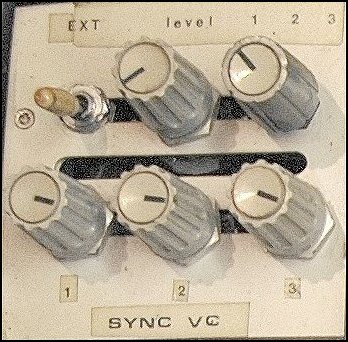
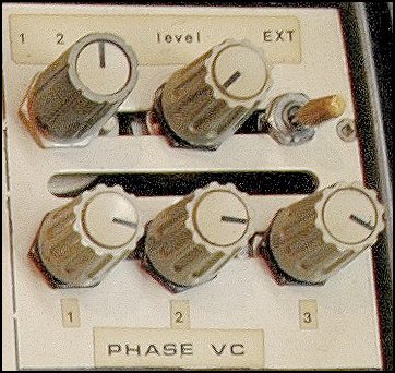
These pots are trimming the input for the target oscillators, not the output of the source. The modulation-signal comes straight from the sawtooth-outputs of the 3 oscillators at full level. These pots are necessary to create different kinds of modulation for the sync or phase. If just a switch was used for a direct connection, only a 100 % follow would be possible. Especially with the sync, this offers nice 'playful' options : If the 'influence' of the modulation is regulated, then the oscillator will create 'natural harmonics'. As a result of a lower level of influence, the target oscillator can't produce the frequency of the source oscillator any more and tries first for the next, neighbouring octave. Whether it will be a higher or a lower octave, depends on the difference in frequency between source and target osc. Not only octaves can be produced, but also sub-harmonics, like 'fifths' and so on. So, with a delicate setting, this will mean that, if the source osc. plays a melody, the target osc. will play a, per definition harmonic, 'second voice'. In case of a frequency-sweep of the source osc. by the Trapezoid voltage of the Envelope Shaper, e.g. from high to low, the target osc. will play a scale of notes instead of 'gliding along'. I call the harmonics 'natural' because they behave according to the laws of physics, of nature. So just numbers are involved, with straight formula's for division and multiplication. A sync example made with Osc 1 (Left) syncing Osc 2 square (Right). Osc 1 is steady, the freq. of Osc 2 is controlled by playing with the joystick. Note that, as long as the own freq. of Osc 2 is lower than Osc 1, discrete lower harmonic tones are formed, while in the 2nd part, when Osc 2 is higher than Osc 1, it is more the same tone, but with higher harmonics. A shape example with Osc 2 modulated by Osc 3. The triangle shape of Osc 3 is varied, and at the end switched to a higher frequency. In both cases one could use the "master/slave" metaphor, but I prefer "modulator/carrier" as with a vocoder. Playing tip : turning the 'Shape' pot of each involved oscillator can make a significant difference in response. | |
Circuit points
|
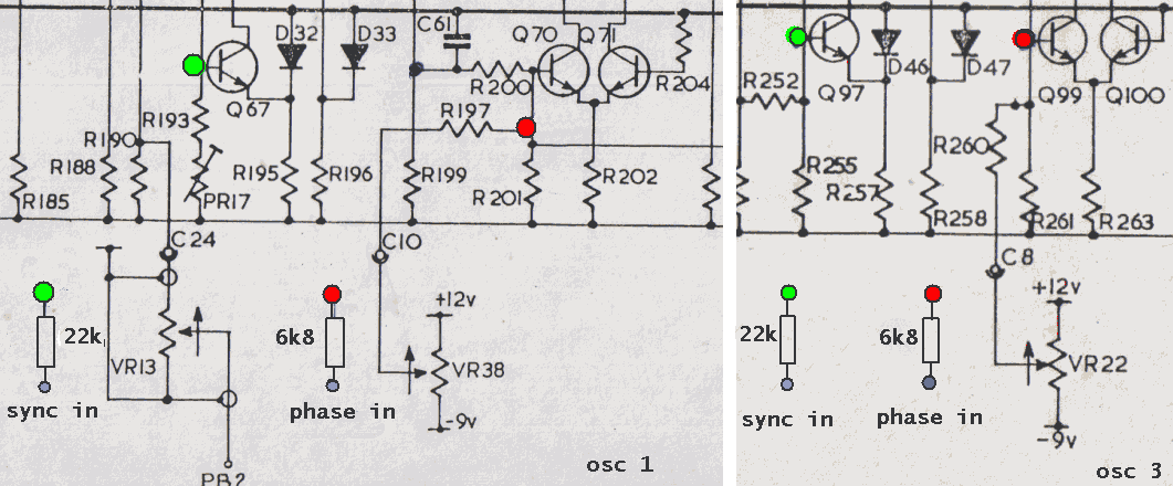
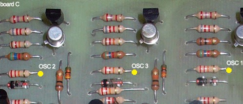
This is a part of the diagram of Osc. 1 and 3 with the connection points for sync and phase control. The source is the same : the 'top' of the trianglewave output pot of another oscillator. The contact points as control input are all at the base of a transistor. Osc 1 : sync - Q67 phase - Q70 Osc 2 : sync - Q81 phase - Q83 Osc 3 : sync - Q97 phase - Q99 Sync has to be connected via a 22K resistor. Phase via 6K8. The sync-points of the oscillators on PCB "C" : |

|
|
Another view, made by Pin : |
|