|
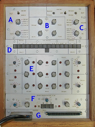
The urge to build this unit came from the observation that on one side there was the freedom of the patchboard, on the other there were some obvious, often-used connections like : ~ The SEquencer-voltage from the AKS to the RingModulator for a percussive output .. ~ The Real-Time-voltage from the AKS to one of the 3 oscillators for playing .. So a reed-relay instead of placing a pin .. Followed by pots to pre-tune the oscillators on the same octaves from different control-voltages .. The other urge was to have an interception-unit of the cable between the AKS and the Synthi. In previous versions of this contraption I already managed to have pre-tuning facilities of the voltages and wider control over the Envelope-Shaper trigger. Plus the option of Portamento ('glide') on the modulation by simply connecting a capacitor from the control voltage to ground. |
| A |
Input-switches for VC1, VC2, VC3 ( patch-rows 16, 8 and 9 ) Sources : Two from AKS (SEquencer and Real-Time), two DAC's and two ext. DC-inputs. |
| B |
Two 6-bits Digital-Analogue Converters. Circuit is a copy of that of the AKS. So one bit for the trigger-pulse and five for the voltage-conversion. Pots for DC-range and pre-tuning. Two 9-p D-connectors at the back for logic inputs. |
| C |
Input-switch for trigger of Envelope Shaper of the Synthi. Sources : AKS (SE and RT), 6th bit of DAC's, plus 2 external inputs (backside). Switches for pulse-length and threshold. |
| D |
The main switchboard for prepared voltage-control. All possible connections between the three oscillators and the three voltages VC1,2,3. Plus on/off Portamento for oscillators 1 and 2. Plus an All-reset to disable the unit. |
| E |
Tuning-pots for all the combinations of connection. Switches for the Portamento-speed. |
| F |
The Ring-Modulator section . Choice of input of column 'F' on patchboard. Sources : AKS (SE and RT) voltages and four external inputs. Switch between 2 input-choices. Switch for diff. speed of 'portamento'. |
| G |
Connector left : to patchboard Synthi (soldered to a 'preset block'). Connector right : Remote Control of all switches involved. |
More details about
A + B + C - D + E - F + G - Backside